Chapter 3 Block Diagrams And Signal Flow Graphs
Control Systems Signal Flow Graphs Tutorialspoint
Signal Flow Graph
Control Chap3
Http Web Engr Oregonstate Edu Webbky Mae4421 Files Section 202 20block 20diagrams 20 20signal 20flow 20graphs Pdf
Signal Flow Graph
Problem 2 On Converting Block Diagram To Signal Flow Graph Youtube

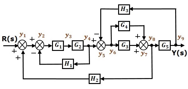
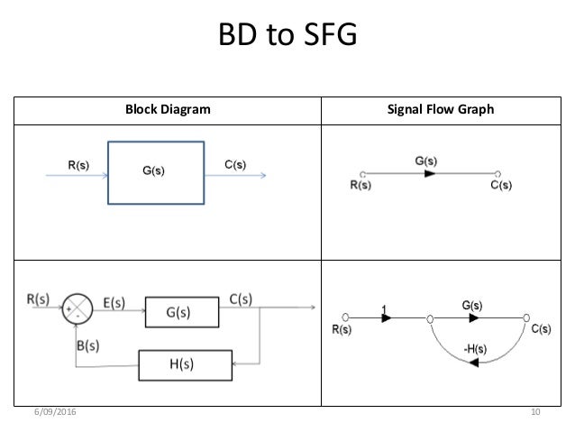
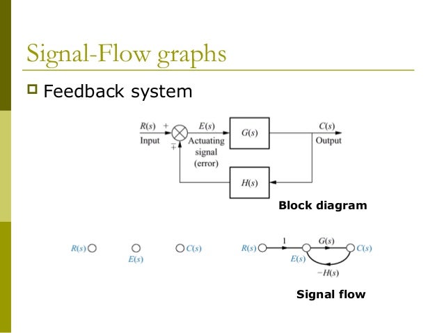
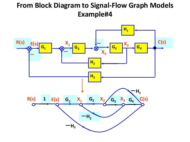
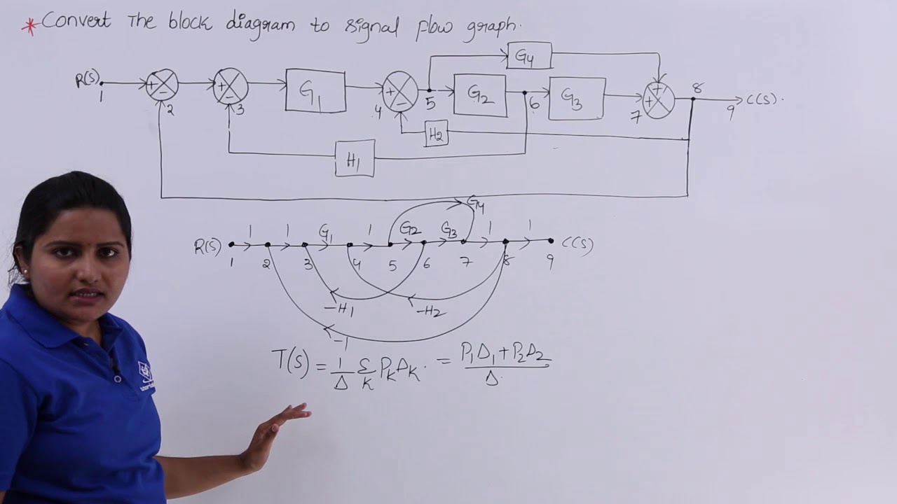
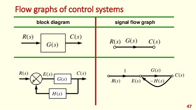
Conversion of block diagrams into signal flow graphs.
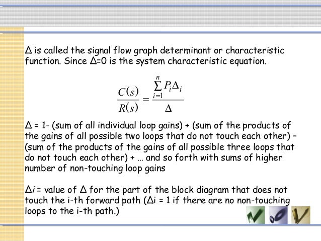
Chapter 3 block diagrams and signal flow graphs. To study block diagrams their components and their undlderlying mathematics. Information in chapter 2 we have looked at how to produce a transfer function from differential equations representing a physical system. Block diagram signal flow graphs gate objective numerical type questions question 6 practice book gate ec 1994 iit kharagpur. 5 marks reduce the signal flow graph shown in figure below to obtain another graph which does not contain the node e5.
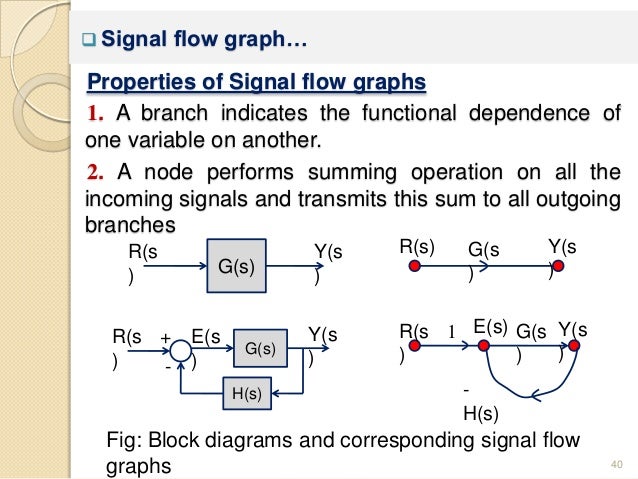
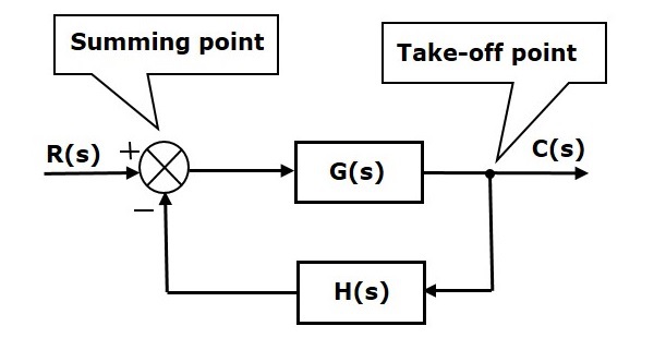
J 1 ra las power amplifier current feedback 2 k u a 4 w i t in 1 j s b tachometer feedback 4 f l gear iuuu a 0 k figure 3p 7 3 8. Also remove any self loop from the resulting graph. For some authors a linear signal flow graph is more constrained than a block diagram in that the sfg rigorously describes linear algebraic equations represented by a directed graph. Represent all the signals variables summing points and take off points of block diagram as nodes in signal flow graph.
To introduce the signal flow graphs. For other authors linear block diagrams and linear signal flow graphs are equivalent ways of depicting a system and either can be used to solve the gain. Objectives of this chapter 1. Follow these steps for converting a block diagram into its equivalent signal flow graph.
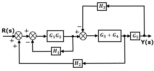
The block diagram of a feedback control system is shown in fig. To obtain transfer function of systems through block diagram maniltiipulation and redtiduction. Step 6 signal flow graph of overall system is shown in the following figure. Find the following.
Each component in a control system has a transfer function these components are combined to produce a block diagram we will look at wars to simplify complex block diagrams at the end of this topic chapter 3 you should be able to apply block diagram.
Signal Flow Graph And Mason S Gain Formula Electronics Club
Chapter 3 Mathematical Modeling

Chapter 6 Digital Filter Structures And Designs Section Ppt
Control Systems Block Diagram Reduction Tutorialspoint

Signal Flow Graph Part 5 With Images Graphing Algebra
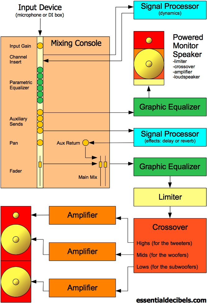
Live Sound Explained 3 The Pa System Signal Flow Diagram

Tutorial Flow Graphs Direct Form Ii Youtube
Signal Flow Graph
Control Systems Block Diagrams Tutorialspoint

Block Reduction Technique Blocks Electrical Engineering Block

Control System Solved Examples Of Mason S Gain Formula

Mason S Rule For Block Diagram Controls Youtube
Modern Control Lec 02 Mathematical Modeling Of Systems