Cfl42 Dimming Ballast Wiring Diagrams

It shows the parts of the circuit as streamlined forms and the power and also signal connections in between the gadgets.
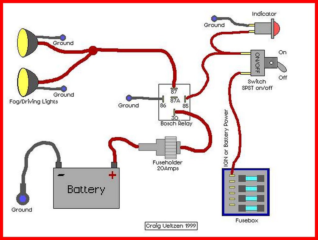
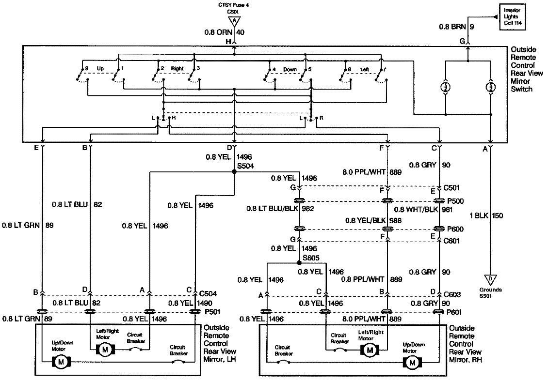
Cfl42 dimming ballast wiring diagrams. Application note 28 appendix b. Variety of dimming ballast wiring diagram. Parallel ballasts can only be wired in parallel according to the diagram on the ballast. A wiring diagram is a streamlined standard photographic representation of an electric circuit.
A set of wiring diagrams may be required by the electrical inspection authority to embrace connection of the residence to the public electrical supply system. Refer to the table in our catalog for the required ballast before referencing any diagram. Dimming ballasts are available for fluorescent tubes and cfls that use an external ballast. 8 fluorescent dimming systems technical guide socket wiring socket wiring for t8 and t12 linear for ballasts that control more than one lamp sockets wired to the yellow or blue with white stripe leads of the ballast must be wired in parallel not in series.
Wiring diagrams and descriptions to help you understand fluorescent ballasts. Visit the post for more. Changing the wiring on a fluorescent light fixture from series to parallel. 0 10v dimming wiring diagram 0 10v dimmer switch leviton ip710 lfz or equal for other types of dimming control systems consult controls manufacturer for wiring instructions switched hot black switched hot red typical low voltage dimming wires purple gray typical electrical panel hot black typical 120v or 277v 60 hz neutral white.
Fluorescent dimming systems technical guide 02 lutron fluorescent dimming ballasts 04 how it works 05 lamp. The ballast data tables in our catalog indicate the page number and reference letter corresponding to the correct diagram for each ballast product. Socket wiring for t8 and t12 u bent correct sockets wired in parallel typically yellow. A wiring diagram is a simplified conventional pictorial representation of an electrical circuit.
Step dimming wiring diagram wiring diagram fascinating 2 bulb t8 ballast wiring diagram wiring diagram meta. 13 sockets and lampholders 16 lamp wiring diagrams 19 ballast control types 20 ecosystem ballasts 22 emergency backup ballast 24 ballast troubleshooting 25 installation best practices 26 appendix a. Led dimming wiring diagram capacitor rh 41 sbaphotography nl light fixture how to setup dimmable led high bay or parking lot lights with 0 rh ledlightexpert com mark 7 10v dimming ballasts wiring diagram advance dimming ballast wiring diagram online diagramadvance mark 7 electricity siteadvance mark 10 ballast wiring diagram todays rh 17 8 9 1813weddingbarn com t8. Dimming fluorescent lights are usually found in commercial and institutional environments and not common in the household.
Variety of 0 10v dimming ballast wiring diagram. Wiring diagrams for venture hps and remote ballast products are provided on this page.


